- 您现在的位置:买卖IC网 > Sheet目录510 > SI4840-DEMO (Silicon Laboratories Inc)SI4840 DEMO AND EVAL BOARD
�� �
�
�Si4840/44-DEMO�
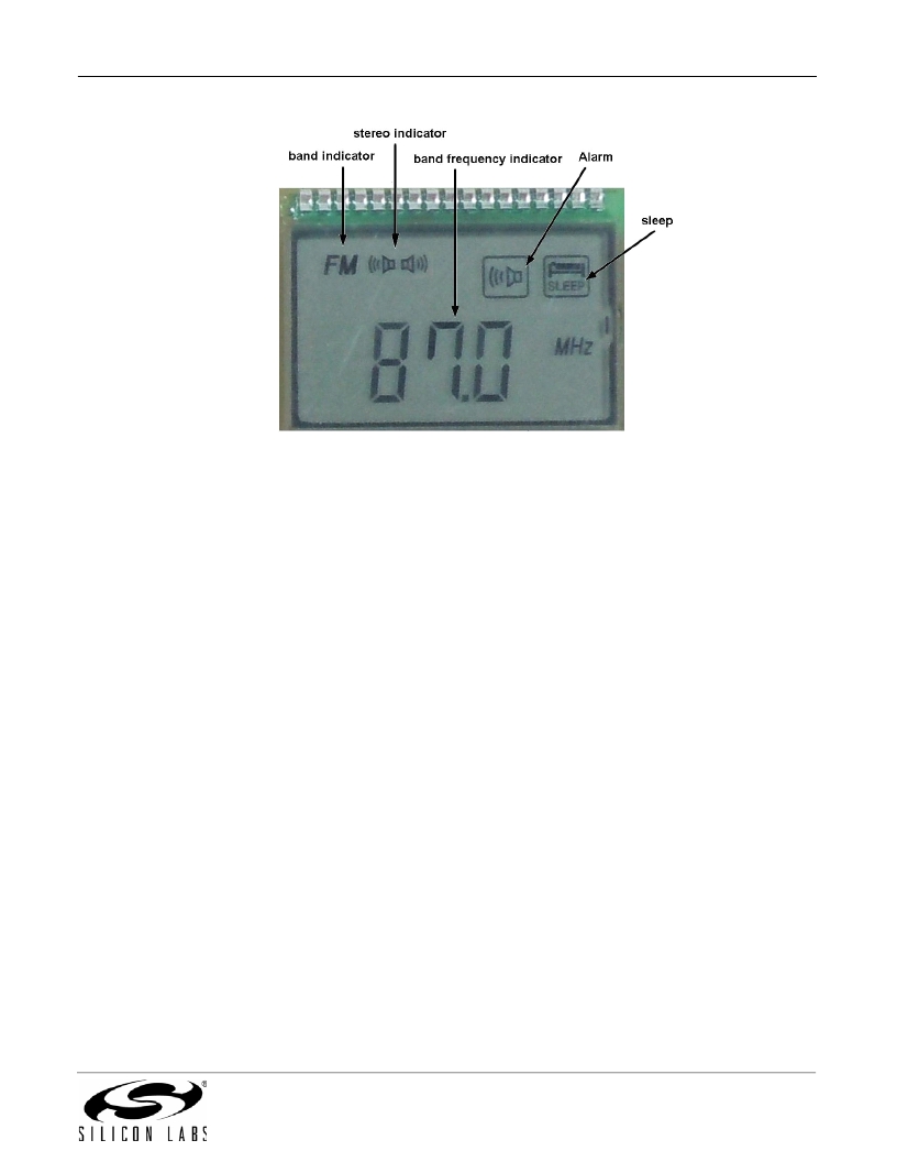
�Figure� 3.� LCD� Display� in� FM� Radio� Mode�
�The� demo� board� provides� two� methods� to� select� the� radio� band.� One� is� to� use� the� slide� switch� (S2).� The� other� is� to�
�use� the� POWER/BAND� push� button.� S14� determines� which� method� is� in� use.�
�The� demo� board� also� provides� two� methods� to� set� the� band� property.� One� is� to� use� the� tuner� default� values;� the�
�other� is� to� use� the� keypad� to� reconfigure� the� band� property� value� via� the� MCU.� S13� determines� which� method� is� in�
�use.� If� you� use� the� tuner� default� values,� the� band� property� is� fixed� and� cannot� be� reconfigured.� Refer� to� section�
�“4.2.1.� MCU� Setting� Band� Property”� for� the� operation� details� for� setting� the� band� property� using� the� keypad.�
�To� operate� the� demo� board,� follow� these� procedures:�
�1.� According� to� the� desired� radio� band� selection� method,� set� S14� to� use� the� slide� switch� or� push� button.�
�2.� According� to� the� desired� radio� band� property,� set� S13� to� use� tuner� default� values� or� reconfigure� the� band�
�property.�
�3.� Hold� the� POWER/BAND� push� button� (hold� time� >1s)� or� when� the� alarm� time� is� reached,� the� device� will� enter�
�FM/AM/SW� Radio� Mode.�
�4.� Use� slide� switch� S2� or� press� the� POWER/BAND� push� button� to� select� the� desired� band.�
�5.� Refer� to� section� “4.2.1.� MCU� Setting� Band� Property”� or� section� “4.2.2.� MCU� Setting� Radio� Working� Mode”� to�
�reconfigure� the� band� property� or� radio� working� mode� if� necessary.�
�6.� Rotate� the� turning� wheel� and� find� the� desired� radio� station� with� the� help� of� the� LCD� display� and/or� tuning�
�indicator� D1.�
�7.� Rotate� the� volume� control� wheel� VR2� and/or� press� the� DOWN/VOL-� or� UP/VOL+� button� to� get� a� comfortable�
�volume.� Press� the� BASS/TMR� or� TREBLE/AL� button� to� get� the� desired� bass/treble� level.�
�Notes:�
�?�
�?�
�For� FM� listening,� the� earphone� cable� must� be� connected� to� the� board� when� S12� is� set� to� HP� ANT� or� an� external�
�antenna� must� be� connected� to� the� BNC� connector� when� S12� is� set� to� BNC.�
�For� AM� listening,� the� ferrite� antenna� must� be� connected� to� the� board� and� the� S11� is� set� to� Ferrite� before� turning�
�on� the� radio� or� switching� the� band� to� AM.�
�Rev� 0.1�
�11�
�发布紧急采购,3分钟左右您将得到回复。
相关PDF资料
SI4842BDY-T1-E3
MOSFET N-CH 30V 28A 8-SOIC
SI4844-A10-GU
IC AM/FM RX FOR DIGITAL RADIOS
SI4848DY-T1-GE3
MOSFET N-CH 150V 8-SOIC
SI4866BDY-T1-E3
MOSFET N-CH 12V 21.5A 8-SOIC
SI4866DY-T1-GE3
MOSFET N-CH 12V 11A 8-SOIC
SI4884BDY-T1-GE3
MOSFET N-CH D-S 30V 8-SOIC
SI4886DY-T1-GE3
MOSFET N-CH 30V 9.5A 8-SOIC
SI4890BDY-T1-E3
MOSFET N-CH 30V 16A 8-SOIC
相关代理商/技术参数
SI4840DY
功能描述:MOSFET 40V 14A 3.1W RoHS:否 制造商:STMicroelectronics 晶体管极性:N-Channel 汲极/源极击穿电压:650 V 闸/源击穿电压:25 V 漏极连续电流:130 A 电阻汲极/源极 RDS(导通):0.014 Ohms 配置:Single 最大工作温度: 安装风格:Through Hole 封装 / 箱体:Max247 封装:Tube
SI4840DY-E3
功能描述:MOSFET 40V 14A 3.1W RoHS:否 制造商:STMicroelectronics 晶体管极性:N-Channel 汲极/源极击穿电压:650 V 闸/源击穿电压:25 V 漏极连续电流:130 A 电阻汲极/源极 RDS(导通):0.014 Ohms 配置:Single 最大工作温度: 安装风格:Through Hole 封装 / 箱体:Max247 封装:Tube
SI4840DY-E3
制造商:Vishay Siliconix 功能描述:MOSFET Transistor Transistor Polarity:NP
SI4840DY-T1
功能描述:MOSFET 40V 14A 3.1W RoHS:否 制造商:STMicroelectronics 晶体管极性:N-Channel 汲极/源极击穿电压:650 V 闸/源击穿电压:25 V 漏极连续电流:130 A 电阻汲极/源极 RDS(导通):0.014 Ohms 配置:Single 最大工作温度: 安装风格:Through Hole 封装 / 箱体:Max247 封装:Tube
SI4840DY-T1-E3
功能描述:MOSFET 40V 14A 3.1W RoHS:否 制造商:STMicroelectronics 晶体管极性:N-Channel 汲极/源极击穿电压:650 V 闸/源击穿电压:25 V 漏极连续电流:130 A 电阻汲极/源极 RDS(导通):0.014 Ohms 配置:Single 最大工作温度: 安装风格:Through Hole 封装 / 箱体:Max247 封装:Tube
SI4840DY-T1-E3
制造商:Vishay Siliconix 功能描述:MOSFET TRANSISTOR TRANS POLARITY (NW)
SI4840DY-T1-E3
制造商:Vishay Siliconix 功能描述:MOSFET
SI4840DY-T1-GE3
功能描述:MOSFET 40V 14A 3.1W 9.0mohm @ 10V RoHS:否 制造商:STMicroelectronics 晶体管极性:N-Channel 汲极/源极击穿电压:650 V 闸/源击穿电压:25 V 漏极连续电流:130 A 电阻汲极/源极 RDS(导通):0.014 Ohms 配置:Single 最大工作温度: 安装风格:Through Hole 封装 / 箱体:Max247 封装:Tube